
Wiring methods for the series and parallel use of proximity switches
Proximity switches, also known as proximity sensors, have certain applications in many fields. Proximity sensors have the advantages of high stability, long service life, low power consumption, high action response frequency, and water and dust resistance. When wiring a proximity switch, the wiring method is rather complicated. Users must master certain wiring knowledge in order to install the proximity switch correctly and quickly.
So, what is the correct wiring method for proximity switches?
(1) Proximity switches can be classified into two-wire and three-wire types. The working voltage of two-wire proximity switches is divided into AC (alternating current) and DC (direct current) power supplies, while three-wire proximity switches are further classified into NPN type and PNP type. Their wiring methods are different. Duokai Company also produces four-wire products. The four-wire system realizes dual signal terminals of normally open (NO) and normally closed (NC) on the basis of the three-wire system, reducing inventory and costs for customers.
(2) The wiring method of two-wire proximity switches is relatively simple. After the proximity switch is connected in series with the load, it can be connected to the power supply. For DC power supply products, the red (brown) wire needs to be connected to the positive terminal of the power supply, and the blue (black) wire needs to be connected to the 0V (negative) terminal of the power supply. This is not required for AC power supply products.
(3) Wiring of three-wire or four-wire proximity switches: Connect the brown wire (BN) to the positive (+) terminal of the power supply; Connect the blue wire (BU) to the 0V (negative) terminal of the power supply. The black wire (BK) or the white wire (WH) is the signal terminal and should be connected to the load.
(4) The wiring for three-wire or four-wire loads is as follows: Except for the end of the load connected to the proximity switch signal, for NPN type proximity switches, the other end of the load should be connected to the positive (+) terminal of the power supply. For PNP type proximity switches, the other end of the load should be connected to the 0V (negative) terminal of the power supply.
(5) The load of the proximity switch can be a signal light, a small relay coil, or a digital input module of a programmable logic controller (PLC).
(6) For programmable logic controllers (PLCS), special attention should be paid to the type selection of three-wire or four-wire proximity switches connected to the PLC’s digital input module. PLC digital signal input modules can generally be divided into two types: The common input terminal of one type is the power supply of 0V, and the current flows out from the input module (Japanese mode). At this time, an NPN type proximity switch must be selected. The common input terminal of another type is the positive terminal of the power supply, and the current flows into the input module (European mode). At this time, a PNP type proximity switch must be selected. Don’t make the wrong choice!
(7) Due to the limitations of working conditions, two-wire proximity switches generate a certain voltage drop when conducting and a certain residual leakage current when cutting off. These factors should be taken into account when selecting. Although three-wire proximity switches have an additional wire, they are not troubled by unfavorable factors such as residual leakage current, and thus are more stable and reliable in operation.
The usage methods of proximity switches in series and parallel
① Two-wire sensor series connection:

Vs-n ×VR≥ the operating voltage of the load (VS: power supply voltage; N: Number of connectable sensors; VR: Residual Output Voltage of Proximity switch. Take the E2E DC 2-wire connected MY DC24V relay as an example:
The operating voltage of MY DC24V is 80% of the rated voltage, that is, DC24V× 80% = DC19.2V. The residual voltage of E2E DC 2-wire type is below 3V. According to the formula calculation: 24-N×3≥19.2, we get N=1.6 (units). Theoretically, series use is not allowed.
However, since the residual voltage of the E2E DC 2-wire type below 3V is not a fixed value, it may actually be smaller. Moreover, MY DC24V can ensure that it definitely operates at 80% of the rated voltage, but it may also operate at 30-80% of the rated voltage. Therefore, the specific number of series operations depends on the actual situation.
② Three-wire sensor series connection:

iL+ (N-1) ×i≤ the upper limit value of the control output of the proximity switch VS-N ×VR ≥ the operating voltage of the load;
(iL: Load current; N: Number of connectable sensors; i: The consumed current of the proximity switch) (VS: Power supply voltage; VR: Residual Output Voltage of Proximity switch. Take the E2E DC 3-wire connected MY DC24V relay as an example:
The rated current value of MY DC24V is 36.9mA. The consumption current of the E2E DC three-wire type is below 13mA. The switching capacity of the E2E DC three-wire type is below 200mA.
According to the formula: 36.9 + (N – 1) by 13, 200 or less to 24 – N * N 13.5 (Taiwan) or less 3 acuity 19.2 to N = 1.6 (Taiwan)
Because MY DC24V can guarantee that it will definitely operate at 80% of the rated voltage, but it may also operate at a voltage lower than 80% of the rated voltage, when the MY DC24V relay is used as a load, the number of connected sensors is limited to 2.
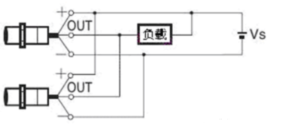
③ Parallel connection of two-wire sensors:
N×i≤ the reset current of the load
(N: Number of connectable sensors; i: The leakage current of the proximity switch. Taking the E2E DC 2-wire type connected to MY DC24V relay as an example: The leakage current of the E2E DC 2-wire type is 0.8mA
The reset current of MY DC24V is 10% of the rated consumption current, that is, 36.9× 10% = 3.69mA. According to the formula calculation: N×0.8≤3.69, thus N≤4.6 (units). When the MY DC24V relay is the load, the number of connected sensors is limited to 4 units.
④ Parallel connection of three-wire sensors:
The three-wire proximity sensor has no leakage current, so there is no need to consider the reset current of the load. Generally, it is recommended to connect three units in parallel.